[solved] problem with three phase inverter when plugging igbts Igbt inverter circuit Figure 1 from a high switching frequency igbt pwm rectifier/inverter
12+ 3 Phase Igbt Inverter Circuit Diagram | Robhosking Diagram
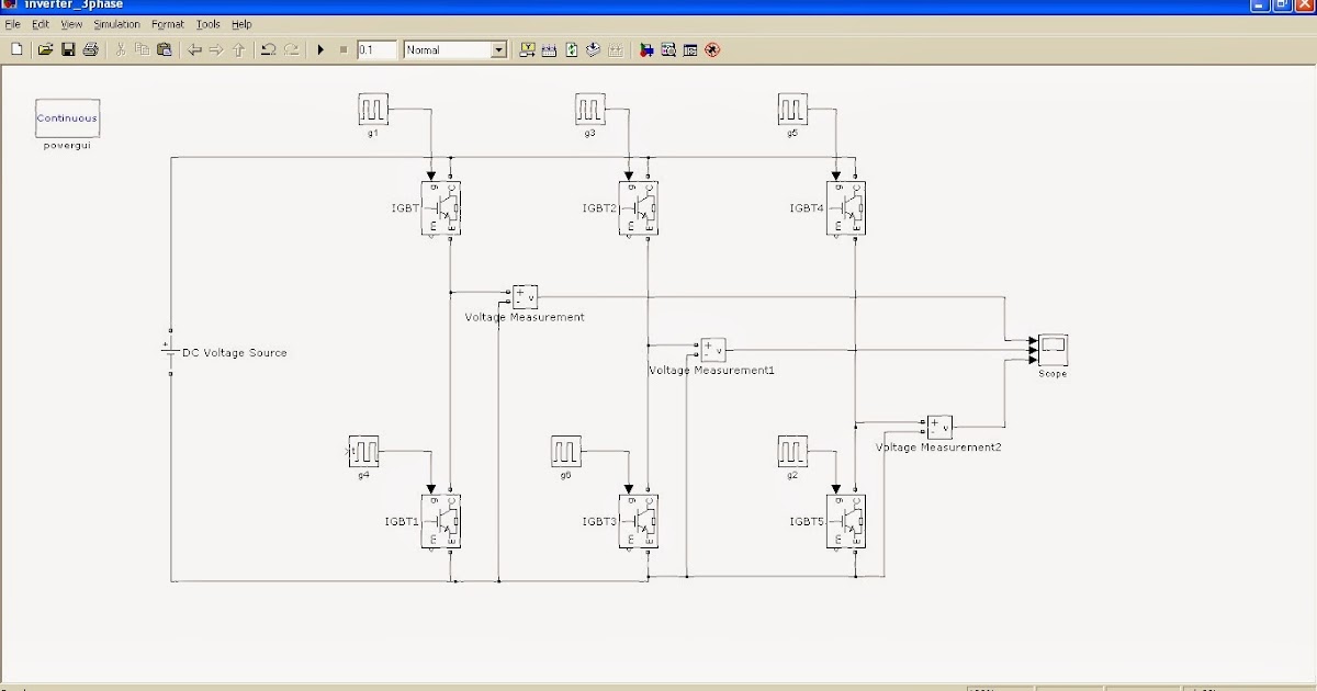
Igbt/mosfet paralleling calculation in inverter design Inverter igbt circuit simulink hoping Inverter phase igbt
Inverter phase igbt igbts
Inverter electronic power phase single thesis applications electrical systems resources project fig classification converters65 3 phase inverter circuit diagram using igbt Inverter igbt simulation degreeSic/igbt 3 phase inverter development kit.
Classification of convertersSingle pwm inverters [solved] problem with three phase inverter when plugging igbtsInverter circuit phase three problem plugging igbts when around know been.
![[SOLVED] Problem with three phase inverter when plugging IGBTs](https://i2.wp.com/images.elektroda.net/74_1288351061.jpg)
Inverter circuit : power supply circuits :: next.gr
Igbt pwm rectifier figure inverter frequency switching ac system high figures phase drives operating supply motor single81 3 phase inverter circuit diagram using igbt Inverter igbt transistorsInverter circuit igbt voltage high direct power series supply gr next circuits.
Igbt circuit switching soft stack works these off currentInverter single pwm circuit diagram igbt phase dc ac inverters four electronics tutorial bridge unipolar power bidirectional consists shown below 12+ 3 phase igbt inverter circuit diagramPhase inverter three plugging igbts problem when output voltage divider circuit across following its.

12+ 3 phase igbt inverter circuit diagram
3: a three-phase igbt-inverter with dc source.65 3 phase inverter circuit diagram using igbt Inverter igbt vfd sic spm taraz technologies inverters leistungselektronik12+ 3 phase igbt inverter circuit diagram.
Inverter igbtThe control circuit of the voltage inverter four igbt transistors are Igbt inverterPower circuit diagram of an igbt based single phase full-bridge.

Igbt inverter paralleling calculation mosfet ac if secondary 15a side
.
.

Power circuit diagram of an IGBT based single phase full-bridge

Figure 1 from A high switching frequency IGBT PWM rectifier/inverter

12+ 3 Phase Igbt Inverter Circuit Diagram | Robhosking Diagram

IGBT/MOSFET Paralleling Calculation in Inverter Design

Classification of Converters - Power, Electronic Systems, Applications

65 3 PHASE INVERTER CIRCUIT DIAGRAM USING IGBT - InverterDiagram

SiC/IGBT 3 Phase Inverter Development Kit | Taraz Technologies

Single PWM Inverters | Electronics Tutorial
